Sunday, September 15, 2013

Fuselage Skins Dimpled For Flush Rivets

The only items worked on during this shop session were the F-1270 left and right fuselage skins. The spar cutout was completed on the F-1270-L fuselage skin using the same procedure that was used to make the cutout on the F-1270-R skin yesterday …. a nibbling tool to remove the metal and a file to smooth out the edges.

Now that the spar cutouts have been completed for both fuselage skins, each skin received a deburring along the edges with files, followed by a final smoothing with the Scotch-Brite wheel and a 3M sanding sponge.
Smoothing the edge of the F-1270-L fuselage skin with a Scotch-Brite wheel.
 
After both F-1270 fuselage skins were deburred and smoothed, they were dimpled using the #30-120 degree dimple dies in Pete’s C-frame. Three areas were purposely not dimpled at this time:
 
1. The previously mentioned NDZ (no dimple zone) where the F-1270A stiffener will be located. This area will not receive any dimples because it will be hidden by the wings.

2. The top row of holes in the F-1270 skins. These holes will be used to match drill into the longerons when the longerons are finally completed. A much more accurate match drilling will be accomplished if the holes are not dimpled when match drilling the longerons. After the longeron match drilling is completed, the top row of holes in the F-1270 skins will be dimpled, the longeron holes machine countersunk and primer sprayed with an airbrush as necessary to prime the longerons and touch up the top row of holes in the F-1270 skins.

3. The rivet holes surrounding the air vent are undersized and are to be match drilled into the vent assembly … that assembly may not be ready before priming, but hoping to complete the air vent parts tomorrow so the match drilling and dimpling can be accomplished before Tuesday … which is the target day for spraying primer.
 
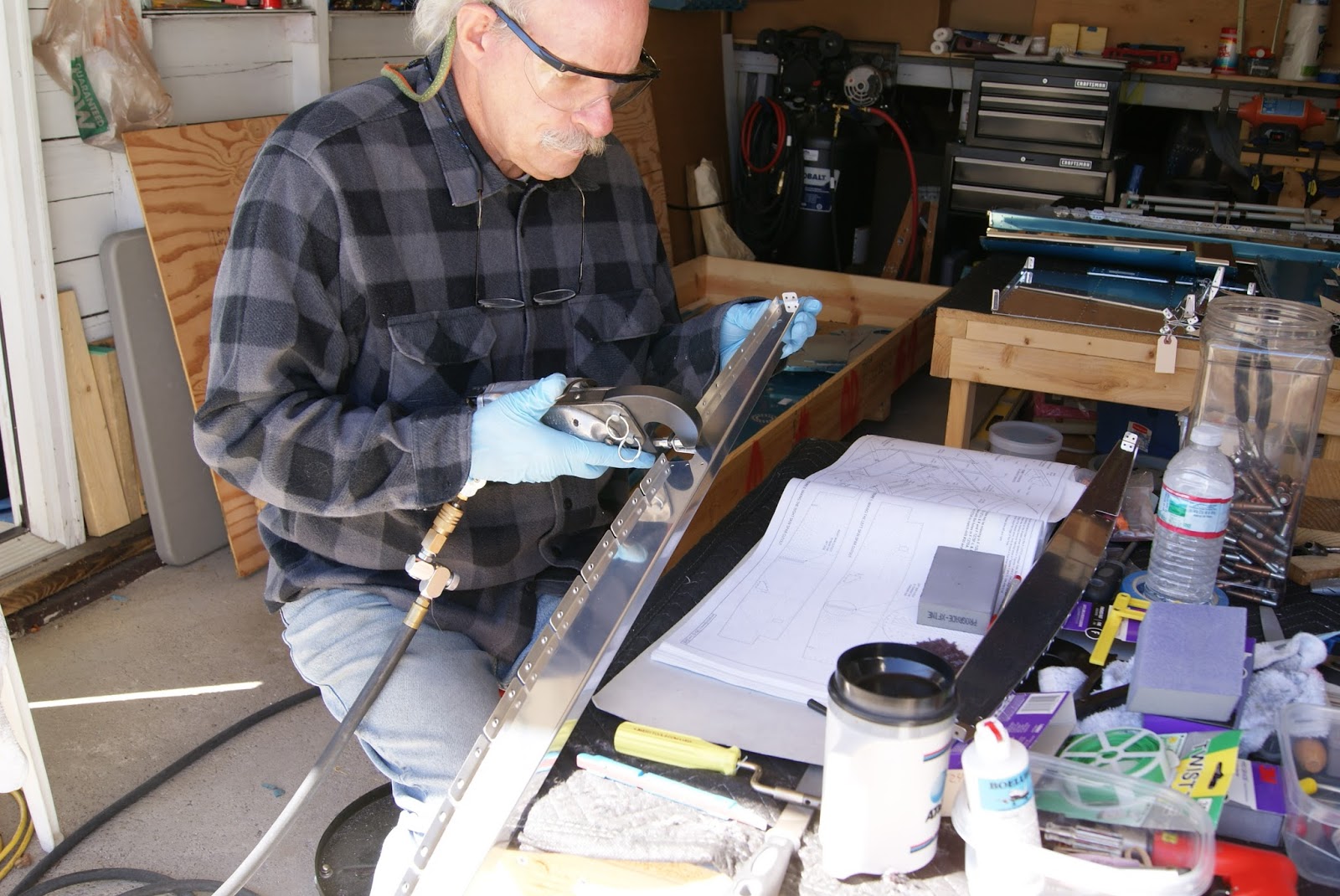
                                     Dimpling the F-1270-L fuselage skin with Pete’s C-frame outfitted with
                                     #30-120 degree dimple dies for the flush rivets being used on the RV-12 project.
              Dimpled F-1270. Looking closely one can see the top row of rivet holes were not dimpled for flush
              rivets at this time, nor were the holes around the rectangular air vent port on the far right.

Side Skin's Wing Spar Cutouts Completed

DOG Aviation had its first taste of fall temperatures Friday night so there was not a lot of enthusiasm for getting an early start in a cold shop knowing the temps later in the day would get to 60. Fortunately, the cold front passing through will be short lived and there promises to be good spray painting weather early in the coming week … so a push is on to be ready for the warmer weather to spray primer and top coat on as many components as possible.

Prior to starting on dimpling, decided to prep the F-1248-L&R armrests. The plans call for cutting a notch into F-1248 armrests in the area where the F-1203G bulkhead side channel  passes through. The locations where the cuts needed to be made were into the piece far enough that the band saw could not be used to make the cuts. The trusty nibbling tool was used to make the cut on both pieces followed by a deburring. Also had the opportunity to use the new sanding sticks and have to say, they work quite well for taking the edge off the aluminum in tight spots.
Using the nibbling tool to cut the required notch in the F-1248 armrest.
Using one of the new sanding sticks to remove a sharp edge on the inside of one of the flanges on the F-1248 armrest.
 
After the armrests were deburred, the pneumatic squeezer was outfitted with the #30-120 degree dimple dies and the armrests were dimpled for the flush rivets being used on the RV-12 project along with the W-1271-L&R corner skins, bottom flange of the F-1217A-L&R tunnel ribs and the W-1272 Forward fuselage skin.

Dimpling one of the F-1248 armrests for #30-120 degree flush rivets with a pneumatic squeezer.
 Placing dimples for flush rivets in all of the rivet holes on a F-1271 forward fuselage corner skin.
Dimpling the bottom flange of the W-1217A-R tunnel rib for flush rivets.
                                            Using Pete’s C-frame outfitted with #30-120 degree dimple dies to
                                            make dimples for flush rivets in the F-1272 forward fuselage skin.
 
Also would like to paint the fuselage side skins during the coming week aswell,  so the F-1270 side skins were removed from the shipping crate for preparation. Both F-1270 side skins are identical. HOWEVER - a cut needs to be made for the wing spar and depending on which side of the aircraft the skin will be placed, will dictate where the cut will be located. Once the spar cut is made, the skin will become a dedicated left or right F-1270. Van’s gives the builder a precut slot which is either extended fore or aft depending on which side of the RV-12 the skin will be utilized. Originally, the plan was to place the W-1270 skin up on blocks and use a jig saw to make the cut but the skin is rather flexi so since the nibbling tool was already on the bench, decided it was much safer to use it. May have taken a few minutes longer, but it was easy to munch away the aluminum with the nibbler and after a few strokes with a sharp file, the slot was completed.
 
It has been mentioned in prior posts in the area where Van’s added the F-1270A side skin stiffener plate the plan is to forgo the use of flush rivets. This being the case, the affected area required being marked onto the skin so the F-1270A stiffener plate was laid onto the fuselage skin and an outline was marked as the NDZ … no dimple zone.
Enlarging the spar slot towards the aft of the skin using a nibbling tool … by doing so, this skin will become the F-1270-R side skin.
Using a marker to trace the outline of the W-1270A stiffener onto the W-1270 side skin to establish the NDZ.
 
The now by default left F-1270 skin was placed on the bench to mark the proper cut marks for the spar slot. As I was about to make the marks DOG Aviation received a visit from a neighbor I had not yet met. He jumped at the opportunity to place weight on the F-1270-L skin to prevent it from moving and supervised the drawing of straight lines.
 
The newly met neighbor eager to lend assistance by keeping the W-1270-L skin pressed tight to the bench.
My new friend supervising the drawing of straight spar cutout lines on the F-1270-L side skin.

Thursday, September 12, 2013

Rains & Cold Temps Delay Parts Priming

The last couple of days have been fairly short work sessions spent preparing more parts for priming by deburring and dimpling for flush rivets. Looking forward in the plans revealed almost all of the parts in section 23 will receive a top coating … most all of them show inside the cockpit. Because the Jet-Flex takes litterely weeks to obtain full cure, decided it best to forge on and get as many interior components finish coated as possible.

The plan was to prime today and topcoat tomorrow but Mother Nature had plans of her own which were not conducive to painting … rain and cold … today the rain, tomorrow the cold. Fortunately, it is just a brief cold front moving through and after the weekend the weather should be perfect for spraying. Probably a blessing in disguise because it will give me the opportunity to prepare both side skins and dimple the parts for flush rivets over the weekend.

Pressing on, the F-1205B roll bar mounting plates were deburred with a file and smoothed in the Scotch-Brite wheel along with the F-1205A and F-1205C mid-fuselage brace and mid-fuselage brace close-out respectively.  The F-1205B roll bar mounting plates should be countersunk but plan to hold off at this time because there may be room to attach them with AN426AD4 rivets as opposed to countersunk pop rivets. Will need to assemble the parts later to see if there is room for squeezing solid rivets ... if so, will countersink to 100 degrees if not then the countersinking must be 120 degrees for the flush rivets called for in the plans. Figure I can still prime and paint now and just use lots of care and countersink later then prime the countersinks with a new tool I received in the mail.
Deburring the F-1205B roll bar mounting plates on the Scotch-Brite wheel.
Deburring F-1205A & F-1205C mid-fuselage brace and mid-fuselage brace close-out using the small Scotch-Brite wheel.
W-1203H-L&R arm rest brackets marked for separation followed by a deburring.
 
The DOG Aviation receiving department accepted delivery of a couple of packages filled with goodies, two of which may possibly interest builders. The new 1.8mm spray gun tip is now in the shop and will be used during the next Jet-Flex spray session … hopefully, it will not prove to be too large of a spray tip and be useful to improve the quality of the Jet-Flex finish. Also ordered with the spray gun tip was a tube of very tiny disposable touch-up applicators. They will come in handy, especially during those rare occasions when machine countersinking a painted part is necessary. They look small enough to paint countersinks without making a mess of things and should be able to make small touchups quite easy.
 
During the return trip from Oshkosh a detour was made to Chicago to visit Marty, a long time friend and Oshkosh AirVenture travel companion. Marty gave me a woodworking catalog which he felt had cool tools that may be of interest to me. While paging through the catalog, ran across some detail sanding sticks which looked promising so they were ordered and just received. Wish I would have had these sanding sticks earlier in the project they are really cool. Thanks Marty!
 
Sanding sticks from Woodcraft ... each stick has a different grit paper and there are plenty of spare sanding belts. The sticks are spring loaded to keep the belt from moving while in use … the stick is compressed so the belt can be rotated to a fresh spot.
 
New 1.8mm spray gun tip for the HVLP gun – hopefully it will work well with the Jet-Flex paint. On the bottom of the photo is a tube of tiny disposable touch-up applicators. If you look closely, there is a small bunch of fine bristles on the end of the applicator.
 
Before closing shop for the night, the F-1203G-L&R bulkhead channels and F-1202E-L&R bulkhead side channels were dimpled for the flush rivets being used on the RV-12 project. The channel’s flanges were measured prior to dimpling and it was determined they were not 90 degrees … so the protractor was used once again to make sure the flange angle could be returned to the proper setting after dimpling.
Dimpling one of the F-1203G bulkhead channel for the 120 degree flush rivets being used on the project.
Using the protractor to check the F-1203G flange angle after dimpling … it only changed a couple of degrees, so was easily tweaked back into the proper angle.

Tuesday, September 10, 2013

Parts Preparation For Section 22 Completed

Today’s work session began with the fabrication of the F-1201L bracket from AA6-063 3/4" aluminum stock. The plans called for a two inch piece to be cut from the stock … a band saw was used to cut the material as well as making two additional cuts on one side of the angle which required two sloped edges. After deburring, the opposite side of the angle was measured and center-punched for the drilling of two #30 holes.
Raw stock to be cut into a two inch piece and made into the bracket shown in the drawing.
Drilling a small pilot hole at the center-punched location on the F-1201L bracket.
The finished hand crafted F-1201L bracket.
 
The VA-188 Flo-Scan bracket is the next item that required deburring, countersinking and ultimately match drilled to the F-1272 skin. Apparently  Van’s uses two types of fuel flow meters and the VA-188 bracket has holes pre-punched for both styles. The builder is required to look at the flow meter to determine which type was shipped with the kit and use the appropriate mounting drawing for that meter. The fuel flow meter shipped with the RV-12 kit was the FT-60, so the appropriate drawing was used to determine which nutplate rivet holes to countersink.
Machine countersinking the nutplate rivet holes on the VA-188 Flo-Scan bracket.
 
After machine countersinking the correct nutplate rivet holes, the VA-188 bracket was secured onto the F-1272 skin with Clecos and the bracket’s mounting holes were match drilled to the skin. Because the RV-12 is being constructed with flush rivets on outside surfaces, the VA-188 bracket will also have the four mounting holes dimpled for the 120 degree flush rivets.
Match drilling the VA-188 bracket to the F-1272 skin.
Using the pneumatic squeezer to dimple the four mounting holes on the VA-188 bracket for the 120 degree flush rivets being used on the project.
 
The last item worked on today was the FF-1204D firewall stiffener. It only required a few strokes with the file and a quick pass on the Scotch-brite wheel to get it nice and smooth.
Smoothing the edges of the FF-1204D firewall stiffener with the small Scotch-brite wheel. Only one side has holes, but the shiny aluminum makes it appear as though both sides of the stiffener has holes.
 
Much to my surprise, preparation of the parts in section 22 parts for primer and top coating (if necessary) was completed today.  Section 23 begins with the fabrication of the longerons and upper fuselage components including the side skins. I know at some point the side skins will be matched drilled to the longerons so just may dimple all the holes except the upper row, prime and paint the interior of the skins. I can then dimple the upper holes after match drilling to the longeron and touch up the primer a bit if necessary.  Doing this will give the Jet-Flex a few weeks to get to full cure and the side skins are a large portion of the interior.  I’m truly worried about the weather and fear if I build now, the opportunity to paint may not present itself later. As much as I hate to say it or think about it, we are approaching the cold season here in the Midwest.

Monday, September 9, 2013

Continuing With More Forward Fuselage Prep

Continuing on with preparing more forward fuselage components for primer, the F-1271-L&R fuselage corner skins were pulled out of the shipping crate and deburred. There was nothing in the plans requiring any preparation for these components … but of course they will be dimpled prior to priming for the flush rivets being used on the project.

While the F-1271 corner skins and F-1272 bottom skin were out of the box, decided it would be a good idea to do a trial fit of them onto the F-1276 bottom skin to identify areas of overlap. Once the pieces were mated, a soldering iron was used to melt the blue film so it could be pealed away from the overlapping areas for primer.
                                     Dragging the soldering iron along the overlapping edges of the F-1271,
                                     F-1272 and F-1276 skins for easy removal of the blue film for primer.

Yesterday, the decision was made to leave the stainless steel firewall components alone until later … today was later. Further in the build, after the F-1217A-R tunnel rib has been riveted onto the F-1201C firewall, the plans have the builder enlarge a hole in the F-1201C firewall to 9/16”. I remember reading builders have had issues with the step drill (unibit) drifting away from center … the drift is caused by the edge of the flange of the F-1217A-R tunnel rib not completely covering the hole which tends to push the step drill away from center. My solution and suggestion to other RV-12 builders is to take an extra 15 minutes now and make a perfectly centered hole by first drilling the F-1201C firewall hole to 9/16”, then Cleco the F-1217A-R tunnel rib onto the F-1201C firewall so the portion of the flange that requires removal can be marked, then removed. Once marked, a Dremel outfitted with a cutting bit was used to hog the excess material, followed by a fine smoothing with a sanding drum. The result … perfection! OK it took at least an extra 15 minutes … time well spent in my book.
              Using the drill press outfitted with a step drill to enlarge the required hole in the F-1201C firewall to 9/16”.

The reason the step drill drifts can easily be seen in the next photo. The flange on the F-1217A-R tunnel rib offers more resistance on the left side of the hole so the step drill will tend to drift right because there is less material there.
            Marking the location on the forward flange of the F-1217A-R tunnel rib which requires removal of material.
                                             Using a Dremel tool with a cutting bit to quickly remove the excess
                                             material on the forward flange of the F-1217A-R tunnel rib.
                           Final smoothing of the F-1217A-R tunnel rib relief with a sanding drum on the Dremel tool.
The finished hole … the F-1217A-R tunnel rib is attached onto the F-1201C firewall .. looks like it was drilled in place.

Moving on, a couple of small F-1201U flat spacers were cut out of raw stock to 1 1/2" each, deburred and set aside for priming.  Next up was the separating of the four F-1257 rudder pedal support channels on the band saw followed by a deburring on the Scotch-Brite wheel.
                          Using the band saw to separate the four F-1257 rudder pedal support channels from one another.

The plans call for dimpling the nutplate rivet holes on the F-1257 channels using #40-100 degree dimple dies. However, only three of the four F-1257 support channels require the nutplate holes dimpled … these dimples correspond to factory dimples already in the F-1201B firewall shelf.
                Dimpling the nutplate rivet holes using the pneumatic squeezer outfitted with #40-100 degree dimple dies.

The plans instruct the builder to also dimple the aft two holes on all the F-1257 rudder pedal support channels to #30-120 degrees flush on the bottom. Those holes can be seen in the above photo marked in red on the F-1257 channels. The corresponding holes (also seen in the above photo) on the F-1201B firewall shelf were also be dimpled to #30-120 degree per the plans.

Sunday, September 8, 2013

Preparing Forward Fuselage Parts

Decided today to continue moving forward through the plans and began preparing forward fuselage parts for primer and top-coating while the weather is still cooperating. The plans at the beginning of Section 22 have the builder doing quite a bit of machine countersinking and some dimpling.  Two nutplate rivet holes are dimpled on the aft side of the stainless steel F-1201C bottom firewall. There are already quite a few factory dimpled rivet holes on the bottom firewall so it seems odd Van’s didn’t dimple the remaining two rivet holes for the fuel return line nutplate. It’s no big deal, so the pneumatic squeezer was used to place the called for #40 dimples into the metal on the aft side of the F-1201C firewall. The bottom firewall still requires more attention, but will continue with it later since the stainless on the firewall won't require primer or paint.

There are two F-1272 tunnel ribs, a left and right. The tunnel ribs will run down the center of the forward portion of the cockpit and create a tunnel for  the fuel lines, electrical wiring, rudder cables, tubing, and probably become a collection point for dropped rivets, lost tools, knuckle skin, etc. as well. After using a file to knock down the edges of the tunnel ribs they were deburred using the Scotch-Brite wheel and some hand sanding. Once smooth, both ribs required quite a bit of machine countersinking on the nutplate rivet holes along the upper flanges. The nutplates will be used to secure the tunnel's cover plate.
                            Using the countersink cage outfitted with a #40-100 degree bit to machine countersink
                            nutplate rivet holes along the upper flange of one of the F-1217 tunnel ribs.

The plans also have the builder place some #30-120 degree machine countersinks along the forward flange of the F-1217 -L&R tunnel ribs at strategic locations. The countersinks on the forward flange of the tunnel ribs must correspond to factory dimples already placed in the F-1201C firewall bottom. To make certain the correct rivet holes would be countersunk, the F-1217 tunnel ribs were placed on the F-1201C firewall and marked accordingly. Note: The F-1217-R has one additional hole to machine countersink for a total of five along its forward flange … the left tunnel rib only receives four countersinks on the forward flange.
                                        Pointing to the four holes on the left and the single hole on the right that
                                        must be machine countersunk in the F-1217-R tunnel rib’s forward flange.

Moving forward, the F-1272 forward fuselage skin was filed and deburred. The plans call for machine countersinking all 26 nutplate rivet holes on the bottom (outside) of the skin. All the nutplate rivet holes were countersunk with a #40-100 degree bit.
                    Machine countersinking all 26 nutplate rivet holes on the bottom of the F-1272 forward fuselage skin.

The last item worked on today was the F-1288 bracket. The bracket comes with a little extra material on it that was removed per the plans using a band saw. The plans tell the builder to machine countersink the upper rivet hole on the  firewall side of the bracket to #30-120 degrees … this countersink will correspond to a factory dimple already on the F-1201C firewall. What the plans fail to mention is you also need to machine countersink #40-100 degree all the nutplate rivet holes in the F-1288 bracket to mate with the factory holes already dimpled in the stainless steel F-1201C firewall. Guess Van’s is trying to see if the builder is paying attention.
F-1288 bracket sitting on the F-1201C firewall after countersinking … the rivet hole being pointed to on the far left requires a #30-120 degree countersink and to mate properly with the firewall, all the #40 nutplate rivet holes also required countersinking … an omission in the plans.