Wednesday, August 24, 2016

Momentous Occasion - DOG Aviation RV-12 Receives FAA Special Airworthiness Certificate

Normally, when an all black SUV with Federal Government license plates rolls up on you at an airport … it’s usually a time for concern. However, that was not the case Monday at the DOG Aviation hangar … in fact, much to the contrary, it was a most welcomed sight. The black SUV’s doors opened and three representatives from the FAA’s Cleveland MIDO (Manufacturing Inspection District Offices) facility exited the vehicle to greet me. Mr. Richard Greenlief, a Senior Aviation Safety Inspector and Small Plane Directorate, was the first to speak and said not be alarmed … normally he would be the only Fed doing the inspection, but he had brought a couple of his newer employees along for some on the job training. I was introduced to Mr Jeffrey Green and Mr. Steven Heard … then was told that Steven Heard would be taking the lead inspector role and would be performing the airworthiness inspection on the DOG Aviation RV-12 under Mr Greenlief's supervision. Steven and I shared an instant camaraderie …. the airworthiness inspection would be a first for each of us.

After the pleasantries were out of the way, the inspection process began with verification of the paperwork I submitted to the FAA. The Rotax engine model and serial number provided by me on the forms were compared to the placard on the engine along with verifying the propeller’s model number. Next the information engraved on the data plate riveted onto the side of the fuselage was verified for accuracy and that it matched the registration PRECISELY, then verification that the N number was correct and on both sides of the aircraft.

The builder’s log was looked at along with the photos taken of me performing the assembly to prove I built more than 51% of the aircraft. A comment was made that it was obvious I built the aircraft over a period of time because the shirts worn in the photos were all different. Guess some guys have tried to claim they built 51% of the aircraft and have showed a hand full of photos with the guy wearing the same shirt in every photo … duh!

A review of the forms that will be sent to Oklahoma City was made along with reviewing the imposed operating limitations, Phase One fly off hours and geographical flight testing area requested by me in the Program Letter sent to the FAA many weeks earlier. For those not familiar with the process, when an experimental aircraft first receives an Airworthiness Certificate the first flights are conducted under restrictions called Phase One. While under Phase One restrictions, the aircraft needs to be flown for a certain number of hours (40 in my case, which is typical for an experimental-amateur built aircraft) and the flights are restricted to within a set geographic area (typically a 25 mile radius from the home airport) … all this is spelled out in the Operating Limitations. Because the typical 25 mile radius would have taken me well into the Cleveland Class B airspace and also over densely populated areas (both a no no during Phase One testing), stating my safety concerns, I requested in the Program Letter (and was granted) a large trapezoid shaped area to the south of my home airport that is predominantly over farm country. I still have approximately the same total square miles to fly within as there would be with a 25 mile radius … but is just in a southerly direction from my home airport. Another stipulation during Phase One testing is no passengers can be taken for rides while still in Phase One testing. When the Phase One testing period is completed after the 40 hours have been flown off … and assuming there have not been any major issues encountered, the shackles are removed allowing the aircraft to freely fly around the country and passengers are allowed to accompany the pilot.

While I was reviewing the above mentioned Operating Limitations, the FAA inspectors were going over the RV-12 making sure the controls moved freely and in the correct directions. The ELT was asked about and an inspection of the instrument panel was made to verify all the controls, switches and fuses had the appropriate labels or placards. After the RV-12 received a good looking over, I was asked to prepare the airplane for an engine start because they wanted to verify there were no oil, fuel or coolant leaks … so the lower cowl was installed, seat pan temporarily set in place along with the seat cushions and the RV-12 was pulled outside the hangar. Because the fuel tank was dry from having done the weight and balance measurements with the required zero fuel in the tank, had to throw a couple of gallons of fuel in the tank for the engine run. After a brief engine run, I was given the signal to shut down so the firewall forward area could be checked for leaks … no leaks were found. The RV-12 was rolled back into the hanger and four years plus a hand full of weeks after construction on the DOG Aviation RV-12 first began, I was awarded the sought after “pink slip” … the FAA Special Airworthiness Certificate.
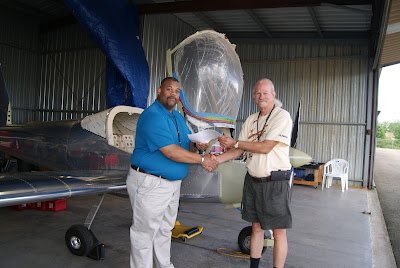
FAA Small Airplane Directorate Mr. Steven Heard presenting me with a “pink slip” … the coveted Special Airworthiness Certificate stapled to the operating limitations.

While the DOG Aviation RV-12 was outside for the run up, Steven took a few photos that he was kind enough to pass on to me which are posted below.
In the background, from left to right Mr. Jeffery Green, Mr. Richard Greenlief and myself.


In the background, Mr Richard Greenlief waiting for me to put some fuel in the tank for an engine start.


So when is the first flight going to be? Not sure honestly. Now that I know I will not need a follow-up appointment with the FAA, the plan is to get some transition training in a RV-12. This will involve traveling to a flight school that has a RV-12 and actually flying one of the factory built RV-12’s. The insurance company is requiring 5 hours of transition training in the RV-12 before I’m covered during the DOG Aviation RV-12’s first flight, but I plan to spend a little more time than that to become VERY comfortable with the RV12. I’m hoping that the transition training can take place sometime next week assuming no issues are found with the flight center’s RV-12 which will be down in a day or so for a mandatory 100 hour inspection.

Monday, August 22, 2016

Lower Cowling Lined With Foil

During the down time while waiting for the upcoming airworthiness inspection, decided it would be a good idea to finish off the lower cowling by installing a self-adhesive protective foil covering that will help protect the fiberglass cowl from the heat of the exhaust pipes and muffler.


Van’s suggests marking the lower cowl adjacent to the location of where the exhaust pipes for the #1 & #2 cylinders pass nearby, then remove the lower cowling and make paper templates that cover the areas marked using a photo shown in the construction manual as reference for the placement of the foil. Once the paper templates are made, they are used to cut the foil to size. Prior to installing the foil, the areas being covered were cleaned with Acetone to help the foil stick better.


My foil was rolled up into such a tight tube that it created wrinkles in the foil that, by in large, were impossible to pull out … especially in the areas where there were compound curves. A Bondo spreader helped smooth some of the wrinkles out and work the foil down tight to the cowl. I wish Van’s would have left the foil flat ... but it is what it is.
Applying the first piece of foil onto the lower cowling.


After the foil is installed onto the cowling, the edges are to be coated with epoxy resin to help prevent them from pealing back over time. I ran out of time so did this in two steps … below is a photo showing the resin coating on the edges of the foil on the sides of the cowling. However, the edges of the foil on the bottom have not yet been coated with resin.
Installed protective foil coating on lower cowling. Note, the edges of the bottom piece of foil still need to be coated with resin to hold the edges down.

Wednesday, August 10, 2016

Fuel Tank Drain Modification Completed

The last remaining construction task on the RV-12 was cutting a hole in the inspection cover under the fuel tank for the CAV-110 fuel drain valve. This will complete a modification to the fuel system that added a sump and fuel drain point under the RV-12’s fuel tank. With the exception of the wheel pants (which will be installed after the RV-12 is painted) drilling the hole for the CAV-110 fuel drain will complete the fuel system modification and marks the completion of construction on the Dog Aviation RV-12 for the time being.


Because the CAV-110 fuel drain valve extends below the belly of the aircraft, it is necessary to cut a hole into the F-1276B cover plate for the valve to protrude through. That created an issue with trying to find the location for the center of the hole that need to be drilled for the fuel valve. I’ve had many months to think about that task and came up with an easy solution. A little liquid Boelube was rubbed onto the flange on the CAV-110 valve, next four 1 ½" #8-32 screws were inserted through the holes in the F-1276B cover plate and started in the nutplates to keep the cover plate aligned with the opening as the cover plate was slid up the screws until it touched the CAV-110 valve which ultimately left a perfect circle of Boelube on the cover plate. The hole was center punched and drilled.
Using a step drill to drill the hole in the F-1276B cover plate for the fuel valve. This is the first of two step drills used to create the 7/8" hole necessary for the grommet.


I opted to use a grommet to make the instillation look finished, so the hole was enlarged to 7/8" to accommodate the grommet that was chosen. A word on the grommet … I looked for rubber grommets at McMaster-Carr but quickly realized they were NOT outdoor rated, so opted to use an outdoor rated silicone grommet.
The grommet chosen requires a 7/8" hole be drilled in the cover plate and has a center hole diameter of 9/16". Unfortunately, McMaster-Carr only sells the grommets in bags of 5 ... good thing they are inexpensive.


The silicone grommets chosen are outdoor rated and have a center hole of 9/16" and required a 7/8" hole drilled in the F-1276B cover plate with a large step drill.
After the hole for the grommet was drilled, the grommet was installed in the F-1276B cover plate.
The completed instillation of the CAV-110 fuel valve modification. The outdoor rated silicone grommet installed in the F-1276B cover plate gives the instillation a finished look. Plus, the grommet is a reddish orange and is easy to spot.

Weights & Balance Measurements Completed

Frequent readers of the DOG Aviation Blog may have noticed there has been a lull in activity as of late … that is because the RV-12 was scheduled for its airworthiness inspection on Monday but earlier last week the FAA inspector called to inform me he would have to reschedule the inspection for later in the month. With that bad news, I have been taking my time chipping away at the necessary tasks that need to be completed prior to the inspection.


Yesterday, completed the last remaining major task that needed to be completed prior to the inspection … the Weight & Balance calculations. This task requires placing all the access panels, cowlings, fairings and associated screws & hardware on the aircraft and installing the seat backs and cushions. No fuel is to be in the fuel tank … but the water and oil are to be left in the engine for the measurement. Not only is the weight of the aircraft measured but the distance from the leading edge of the wing to the center point of each wheel axle is also measured for the necessary calculations.


Prior to making any of the measurements, the aircraft needs to be leveled. Van’s suggests using 2” blocks as a starting point and adjusting down or up from there as necessary. Bernie had loaned me a set of trailer ramps and I found the lowest level of 2” was too high …. after a little playing around with the digital level, discovered a 1 x 12 side from one of the shipping crates was the perfect thickness under the main wheels to level the aircraft at the canopy deck … so the ends were cut at a 45 degree angle so the tires could easily roll up on the boards. With the fore and aft now level, the side to side needed to be leveled as well … this required removing some air from the left tire.
Fore and aft levelness was accomplished by rolling the main tires up onto a 1 x 12.
Left to right levelness was accomplished by removing some air from the left tire.
Rolling both main wheels up onto the 1 x 12 achieved a perfect levelness fore and aft.

Prior to rolling the RV-12 onto the scales to measure the weight on each wheel, measurements need to be taken measuring from the leading edge of the wings to the center of the axles for the wheels. First a center point for the axels on both wheels needs to be established and marked on the floor. The digital level purchased for setting the propeller pitch also has a built in laser that shoots a beam of light which places a  + on the object it is pointed towards. The laser came in handy for finding the center point of the axel and making an accurate mark on the floor directly below the wheel’s axel. Van’s plans suggest using a plum bob hung from the leading edge of the wing to make a mark on the floor in front of the axle for each wheel. I opted to use the 4 foot metal arts and crafts ruler (visible in the above photo) the DOG Aviation procurement department purchased long ago since it was long enough to touch the leading edge of the wing. The edge of metal ruler was placed against the leading edge of the wing and the digital level was used to verify the ruler was 90 degrees to the wing and 90 degreed to the floor …. when the positioning was verified, a mark was placed on the floor, this is done for both main gear wheels. The distance from the leading edge to the center of each main gear axle is measured and recorded on the Weight & Balance form as D1 & D3. A third measurement is required from the center of the nose wheel’s axle to the leading edge “line” … this is D2. This measurement was accomplished by using a metal tape measurer stretched under the fuselage to connect the leading edge marks made previously on the floor for the left and right side measurements for D1 & D3. A measurement is made from that “line” to the center of the nose wheel’s axle. Unfortunately, I forgot to take photos of the measurement process but below is a copy of the Weight and Balance form so one can see what was necessary … hopefully it will make sense after looking at the drawing on the form below.


This is the Weight & Balance form … the measurements explained above were for D1, D2, and D3.

Now for the actual weighing of the aircraft. The DOG Aviation procurement department took a tip from Don a RV-12 builder in Texas and purchased three Smart Weigh digital shipping and postal scales rated to 440 pounds that are quite accurate. I stepped on all three scales and they all showed the exact same weight within a tenth or two of a pound.  Bernie got on the scales and said it was the weight he saw at the doctor’s office the day prior, so I feel pretty confident these postal scales will yield reasonably accurate results. The scales have a remote digital readout and a tare function that was used as explained later.
Three Smart Weigh shipping and postal scales were purchased for measuring the weight on the DOG Aviation RV-12’s wheels.


Measuring the weight on each wheel needs to be done with the aircraft level … this poses a small issue because ramps are need to accommodate the thickness of the scales and the boards used to level the aircraft. Fortunately, the ramps Bernie brought over saved the day after all. Bernie’s ramps were about as high as the scale with the leveling 1 x 12’s sitting on them … so what we did was roll the aircraft’s main gear up onto Bernie’s ramps. Next the two scales for the main wheels were placed in front of the wheels and turned on … once zeroed, the 1 x 12 boards were placed on the scales and the Tare function button was pushed to zero the scales with the wood on the scales. The board and scales were then slid up against the ramps and the aircraft was rolled onto the scales … then the ramps were slid back a little so they would not interfere with the readings. I then went back to the tail cone and pulled down on it while Bernie slid the third scale under the nose wheel. Presto … instant weight readings with the aircraft sitting level on all three scales. A note about the scales … they do time out after two minutes if the weight does not change, so while setting up we pushed on the aircraft’s wings occasionally to prevent a time out until we were ready to take the readings.
The aircraft sitting on the three Smart Weigh postal scales. The two scales for the main gear need the 1 x 12 boards on top of the scales to make the aircraft level. The aircraft was first rolled onto the brown ramps seen behind the main gear. When the scales were in place and zeroed with the boards on the scales, the aircraft was rolled off the ramps and onto the scales as can be seen in this photo. One can see a little air was removed from the left tire to get the aircraft to level side to side.


For fellow RV-12 builders interested in "the numbers", I knew she would be a little “chubby” … with all the accessories (excluding wheel pants yet to be installed), primer, second landing light, interior paint and backup instruments the Eagle weighed in at 746 pounds with an empty arm of 81.01 inches. The wheel weights recorded were … 148.6 lbs. on the nose gear, 289.7 lbs. on the left gear and 307.7 pounds on the right gear.  The D1 measurement was 23 11/16" … D2 was 39 7/8" ….and D3 was 23 13/16". The casual observer may wonder why there is such an uneven weight between the left and right wheels … this is due to the backup instruments, mass of the ELT and its battery/antenna, the oil tank with oil, battery, coolant reservoir, fuel tank/fuel filler neck and associated hardware all being right of center on the aircraft.


A special thanks goes out to Bernie for supplying the ramps which ultimately worked out fantastic and for all the assistance during the Weight & Balance measurement process.

Sunday, August 7, 2016

Testing Of Static/Pitot System & Transponder Completed

One of the checks that was performed earlier in the week was the testing of the Dynon 261 Mode S transponder and the static/pitot systems. The FAA requires transponder testing to take place every two years. Unfortunately, I forgot to bring the camera to the hangar and didn’t think about the camera in my phone, DUH … so don’t have any photos of the setup to share.


The testing is conducted by connecting a very sensitive “test box” to the static ports and pitot tube. The "test box" can simulate flying at various altitudes and airspeeds by varying the pressures on the static ports and pitot tube. The test box also has the capability of decoding the transponder's transmission by covering up the aircraft's transponder antenna with a cup that receives the transmitted signal while at the same time preventing the signal from radiating beyond the aircraft during testing. The goal is to make sure the transponder can transmit “squawk codes” along with reporting the aircraft’s altitude correctly to air traffic controllers.


Fellow RV-12 builders may want to take note of the following: The Dynon manual makes it very clear that when performing the static system/transponder testing, it is CRITICAL  that the SkyView be powered off when making any pressure changes at the “test box” …. Not doing so can damage the sensors in the ADAHRS unit. Because Primary Flight Displays like the Dynon SkyView D1000 are not commonplace yet, test shops are not familiar with this because they are mostly working with “steam gauges” in the typical Piper or Cessna … so don’t take it on blind faith that your test shop is up to speed. I asked the gentleman performing the testing if he had ever tested a Dynon SkyView D1000 system before and aware of the required testing procedure and was told “no”.... at that point I showed him the Dynon manual and had him read the paragraph that spelled out how the testing needs to be performed and why. I was told following the Dynon testing procedure would not be an issue for him, so we proceeded with the testing. Every time the pressure needed to be changed, we powered off the SkyView and when the pressure change was stabilized at “the box” we powered the SkyView back up.


When the testing first began, I was told there was a very large leak in the static system. The test connections at the static ports were checked, but they were OK, meaning the leak was someplace in the static system. Followers of the DOG Aviation Blog know I have run an additional static line from the tail cone up to the instrument panel for the backup instruments … so I thought that would be a good spot to begin troubleshooting the leak. I was praying the problem would not be in the tail cone so opened up the static line coming from the tail cone where it first appears in the instrument panel and capped off the line. This solved the leak issue … it was a HUGE relief knowing the problem was at the instrument panel where things are much easier to get to as opposed to crawling inside the tail cone for a repair.


At this point we added the backup instruments one at a time until the problem was identified to be coming from the vertical speed indicator (VSI). We hooked up the box directly to the VSI and it still failed so the issue was at the VSI itself. After a little inspection with a mirror I discovered the root of the problem. Me! Apparently, I over tightened the fitting on the VSI’s static port and cracked the pot metal casting. This was hard to spot but I noticed a small line on the casting and after scraping away some of the paint, one could see there was clearly a crack. We completed the testing with the static tube going to the backup VSI capped off.


We both learned something interesting regarding the SkyView 261 transponder that also may be of use to fellow RV-12 builders. The Dynon SkyView 261 transponder is a remote unit, so there are no switches or buttons on the unit … as such, all control is done through the SkyView D1000. When we began the actual testing with “the box”, I was asked to place the transponder in the Alt mode so it reports the altitude. Normally, there is a button for this on the transponder, but the Skyview uses function buttons to turn the transponder on and off. But there was no indication appearing for Alt … I was asked if there were any pressure switches installed which verify flight and I said “No”.  So we both came to the conclusion perhaps the SkyView needs to be fooled into thinking it is flying. So “the box” was set up so an airspeed of 90 knots was simulated and the display for the transponder now had a button for Alt. When Alt was selected, it allowed the transponder to begin transmitting the altitude along with the “squawk” code. Learn something every day when building an airplane.


Once the static leak was resolved and the idiosyncrasies of the Dynon Skyview sorted out, the DOG Aviation RV-12 passed with flying colors. I was told the transponder is reporting the altitude within 10 feet which is great! Also, the transponder was able to correctly transmit the various combinations of “squawk” codes that were required for the testing.


When the testing was completed, I immediately picked up the phone and called UMI and fortunately they had a new VSI in stock which they put it in the mail that day for a two day priority shipment. I received the new unit and installed it yesterday … this time I was much more careful when tightening the fitting for the static port. Below is a photo of the cracked casting for the static port on the VSI after some of the paint was removed in the area.
The source of the leak in the static system was traced to a crack in the static port on the UMI vertical speed indicator after flaking some of the paint away. Obviously, the fitting was over tightened by me and the pot metal split where the fitting screws in.

Friday, August 5, 2016

Landing Light Lenses – Instillation Woes

Prior to performing the weight and balance calculations that need to be completed for the airworthiness inspection, every piece of the airplane needs to be installed so accurate measurements can be obtained. One seemingly small task that needed completing was installing the landing light lenses. That small task turned out to take quite a bit of time to get accomplished.


The issue revolved around the W-1223E lens backing strips. Van’s plans call for using double sided tape to stick the backing strips onto the lens then insert the lens into the wing. In order to insert the lens into the opening in the wing the lens needs to be flexed a bit and wedged in behind the leading edge of the wing but in front of the landing light ribs. With all the flexing the backing strips kept popping off. I think the big issue was that I was using the thin double sided tape that looks like Scotch tape … guessing I would have been better served with the thicker foam type double sided tape.


It took quite a while trying different methods to keep the backing strips in place with no real success. Was just about to close up shop to head out and get some of the foam type double sticky tape when an idea came to me that ultimately worked great ... and I can whole heartily recommend it to fellow builders who don’t want to fuss with double sticky tape. I ended up using two lengths of waxed cord (the thin type used for jewelry crafting) looped through the center two holes of the W-1223E backing strips but instead of tying a knot, the waxed cord was twisted a few times so it would hold the strips in position while inserting the lens into the leading edge of the wing.
Because the double sided tape was not working out to hold the backing strips onto the lens, to get the task done waxed cord was looped through the two center holes then twisted a few times. Ultimately this worked out quite well to hold the backing strips in place while the lens was inserted into the cutout in the leading edge of the wing.


After the lens was in an approximate position, the outer two screws were threaded into the nutplates. Once the outer two screws were started, the twists were removed from the wax cords and they were pulled out so the remaining two holes could be secured with screws. The wax cord used was the thinner style found at arts and crafts shops for making jewelry.
With screws in the outer edges of the upper backing strips, the waxed cord was unwrapped and is now ready to pull out. The bottom backing strip is now in position and ready to receive screws in the outer two holes.


After the outer screws are in place and the waxed cord removed, the center two holes on each backing strip received screws to complete the instillation of the lens.
Completed instillation of the landing light lens in the wing … one down one to go.


Gee, this was so much fun … think I will do it again for the additional landing light in the other wing.