Sunday, May 5, 2013

Riveting Of Right Wing’s Top Skins Completed

Continuing where the riveting left off yesterday, the day began by setting rivets into the long, seemingly endless, row of rivet holes that are in the main spar of the RV-12’s right wing. The riveting began in the center of the spar and working towards the outboard and inboard ends of the right wing. Wow! A lot of rivets are in just that one row … ask my back how I know.
                                           Beginning the riveting of the long row of closely spaced rivet holes
                                           which secure the wing skins onto the right wing’s main spar.

After the main spar riveting was completed, riveting continued by riveting the upper wing skins onto the W-1210 ribs one row at a time working from the main spar aft to the rear spar.
Making progress … the finish line is in sight.
Setting the last rivet securing the outboard portion of the W-1203B-R wing skin to the rear spar assembly.
Right wing’s top skins riveted in place with flush rivets.
 
At this point, all of the rivets are in the right wing’s main skins with the exception of the outer edge of the W-1203 and W-1203B skins. The rivet holes on the outer edges of those two skins are left open because the wing’s tip skins will be sharing those holes.

Saturday, May 4, 2013

The RV-12’s Right Wing Closeout Under Way

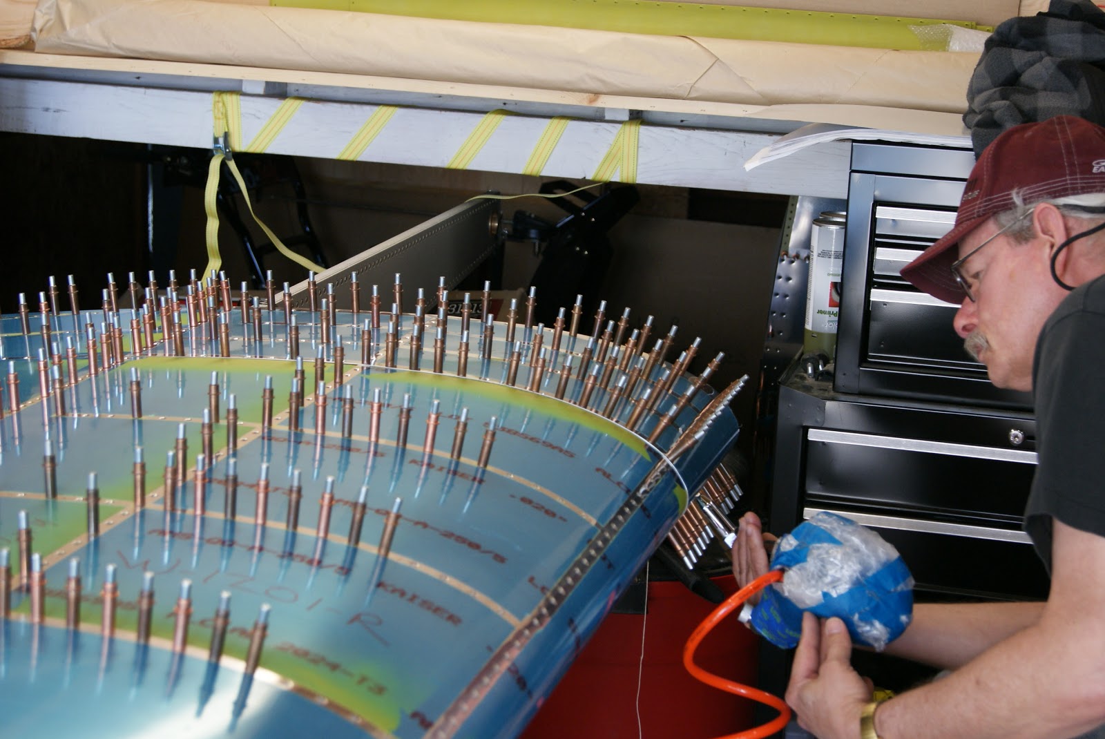
The first order of business today was to finish up placing every available #30 Cleco in the shop into the right wing's W-1201B, 02B and 03B upper skins to secure them onto the right wing skeleton. As with the left wing, Van’s assembly order was modified because the shop is outfitted with enough Clecos to secure all three of the upper wing skins at one time. Riveting began by riveting the leading edge of the wing walk doubler aft to the same point the riveting was halted prior to placing the top skins into position. Riveting then continued by riveting one row of rivets at a time working from the center of the wing towards the outer edges. The removed Clecos were then moved further aft to populate empty rivet holes.
Placing Clecos into the upper wing skins to secure the skins for riveting.
All three top skins are secured with Clecos and ready for riveting to begin.
Using the pneumatic rivet puller to set the first of many flush rivets into the W-1201C-R wing walk doubler plate.
Setting the last flush rivet forward of the main spar.
 
It was getting late so worked was halted for the evening leaving the line of rivets in the main spar as the next location for riveteing when work continues tomorrow.

Friday, May 3, 2013

Green Light Given For Right Wing Closeout

Yesterday, DOG Aviation received another on site visit from Jim, the EAA technical councilor, to inspect the RV-12’s right wing skeleton assembly prior to closing out the wing. Once again the inspection went very well, after inspecting the latest work on the right wing, the green light was given to closing out the right wing.

In preparation for riveting, the blue protective film was removed from along the rivet lines of the three top skins and the edges of the skins received a final sanding.
Using a solder iron and straight edge to melt lines into the blue film so it can be pealed off along the rivet lines.
The W-1201B-R inboard top skin was set in place and “pinned” in position using rivets at those locations which pass through the single flanges on the W-1210 aft ribs which are located underneath the main spar. The rivets are set in place by hand and then verified by using a light and mirror that the rivets go through the flange.
                                Using a flashlight and mirror to verify the rivets used to “pin” the W-1201B-R
                                inboard top skin actually go through the forward flanges of the W-1210 aft ribs.
Setting the W-1202B-R center skin in position.
The W-1201C-R doubler plate for the wing walk needed to have its edge broken. Unfortunately, as with the left wing’s wing walk doubler, the skin was already dimpled so the Cleaveland edge forming tool can’t be used … bummer. RV-12 builders, break the leading edge before dimpling you will be glad you did.
Readers keeping tabs may remember the left wing walk doubler plate was placed against the edge of the workbench and worked with a PVC pipe cap until a small amount of break was achieved. It was a hassle. Hate to admit this, but I actually had a tool that would work but forgot about having purchased it. The Cleaveland tool is the cat’s meow, so the one from Avery went into the deep dark recesses of the tool box and was forgotten about. The other day it was discovered while hunting for a tool so decided to try to use it because the rollers are way way narrower than the ones on the Cleaveland tool. Because of the smaller rollers, the Avery tool can roll along the edge of the skin between the edge and the dimples. It is not easy, but after a few passes I could see the edge was beginning to break.
Using the Avery tool to break the leading edge of theW-1201C-R wing walk doubler plate.
A good look at the small rollers of the Avery edge forming tool.
Now that the wing walk doubler plate was ready for assembly, the skins underneath where the doubler plate will be attached were scuffed with a Scotch-Brite pad, cleaned with Acetone, then sprayed with zinc chromate primer.
Scuffing the area that will be underneath the wing walk doubler to prepare the metal for primer.
Area underneath wing walk doubler primed.
Attaching the W-1201C-R wing walk doubler onto the right wing’s inboard skins with Clecos.

Wednesday, May 1, 2013

Right Wing’s Tip Components Prepared

While waiting for the pre-closeout EAA technical councilor inspection of the right wing tomorrow, work continued on preparing wing tip parts that will be needed later during the closeout.

Yesterday, the forward wing tip rib was dimpled for flush rivets, today the aft wing tip rib was dimpled and an access hole was cut in the wing tip bottom skin for the wing tip navigation/strobe lighting, followed by the bending of all the tabs to the required angle. Followers of this RV-12 build will remember the dimpling of the aft wing tip rib is challenging, but made easy with a method conceived by the DOG Aviation think tank.

The dimples are easily made by using two dimple dies back to back with a washer placed between them INSIDE the rib and a specially fabricated nail to hold the dies in alignment. As the pneumatic squeezer’s piston pushes outward the male tip on the die pushes the nail into a yoke without a set as the dimple is being created. A washer with tape on it is placed between the yoke and the rib to prevent the yoke from marring the rib. This works great!
The setup – pneumatic squeezer and yoke without a set in the hole, two females dimple dies back to back with a washer between them INSIDE the aft wing tip rib. All this is held in place with a specially crafted nail with washer to prevent the yoke from marring the rib.
About to squeeze the dimple … note how the nail will slide into the hole in the yoke as the squeezer’s piston pushes out.
                         After a dimple is made on one side, the nail is removed and placed through the dies from
                         the opposite side so a dimple can be made on the opposite side of the aft wing tip rib.

One side effect I forgot to mention when discussing this process for the left wing is the rib will become slightly deformed because the rib is a U channel … all the dimples will put a small bow in it which needs to be corrected by a little fluting. Builders attempting dimpling of their RV-12 please take note: The aft wing tip rib has a natural bow or curve to begin with … however, the web of the rib which will be the outer edge of the wing needs to be straight and flat but after dimpling, it takes on a small curve as well. This small curve is easily taken out by slightly fluting the rib. Before dimpling, the natural curve of the aft wing tip rib was traced onto a piece of cardboard … after dimpling and the follow-up fluting, the curve can be verified to be close enough to move on.
This is the curve that is normal for the wing tip rib.
While holding the web of the aft wing tip rib onto the edge of a table, the rib is fluted as necessary at the location the rib departs the edge of the table. This will take the curve/twist out of the rib … small amounts of fluting are done to both sides of the rib. This rib is almost perfect now.
After the aft wingtip dimpling was completed, work started on the bottom wing tip skin. Because there will be a navigation/strobe light installed on the wing tip, an access hole needed to be cut into the W-1204D-R bottom skin. The template for the cutout was placed on the skin and the outline for the hole traced onto the skin and then cut with a jig saw.
Drilling holes with a step drill to allow access for the jig saw.
                                          Cutting the wing tip light’s wiring access hole into the W-1204D-R
                                          bottom wing tip skin with a jig saw using a 24 tooth per inch blade.
Smoothing the freshly cut wiring access hole in the W-1204D-R skin with a ScotchBrite wheel.
The last task of the day was bending all the tabs on the W-1204D-R  wing tip bottom skin to the specified angles. The same process that was employed on the left wing to verify the tab angles using a digital level was employed again. First the digital level is placed on the plane the measurement will be taken on ... then the bevel button is pressed to zero the level to the slope of the workbench. The tab is bent to the specified angle using the tool Van’s has the builder fabricate from wood ... then the angle is verified with the digital level.
                                           Using the specially fabricated bending tool to bend one of the tabs
                                           on the W-1204D-R bottom wing tip skin to the specified angle.
Using the digital level in the bevel mode to display the angle of the tab which, in this case, was 30 degrees.
                                           Finished W-1204D-R wing tip bottom skin with freshly cut wiring
                                           access hole in the foreground and bent tabs in the background.