My cozy NOT new place to spend quality time
adorning the wiring with red wire ties.
With the edge of the seat ramp floor poking overly sore ribs (plenty bruised from leaning over the longerons in prior days) continued chipping away at dressing the wiring in the area of the rudder pedals. It is not a hard job, but it is certainly not fun. Work began with wire tying the Molex connector for the fuel flow meter onto the top of the Adel clamp, followed by placing wire ties along the wiring bundle up to the instrument panel.
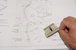
The F-12125 over rudder wireway is a cover plate that will keep the wiring off the rudder pedal assembly. One thing I noticed that I did not like was the possibility of the threads on the mounting screw to rub on the wires. To fix this potential problem area a small piece of heat shrink tubing was placed over the threads in the area the wires will touch.
The mounting screw for the F-12125 over rudder wireway is covered with heat shrink tubing to prevent the sharp edges of the threads from rubbing on the wires.
Getting the pitot tubing and all the wires in the F-12125 over rudder wireway and securing it in position with the screw is somewhat of a challenge. I elected not to even bother trying to place the static air line for the back up instruments in the wireway. Once the final positioning of the wiring is established the static line will be wire tied onto the side of the wire run. The mounting screw for the over rudder wireway was left loose so the wiring can be tweaked as necessary when the rudder pedal assembly trial fitted ... will need to pop a cable or two back in place that popped out.
Wiring all dressed with wire ties and ready for
instillation of the rudder pedal assembly.
Wires and pitot tube running through the F-12125
over rudder wireway. The wireway is not tightened down so the static cable and wires can be final positioned
later.Return from the future: As is often the case, hindsight is 20/20 and if I were to do this again I would seriously consider splitting the wires and tubing so they pass on either side center rudder mounting block. If one looks closely at the above photo - to the right of the F-12125 raceway one can see one of the two nutplates used for mounting the center rudder block – further to the right one can see an unused nutplate in front of the blue fuel line fitting. I feel another F-12125 raceway or Adel clamp could easily be installed here. Research revealed early RV-12’s did not incorporate the F-12125 raceway but used two Adel clamps on either side of the center rudder mounting blocks. The nutplate for the one on the right is still shown on the drawings, so it was installed during the build and is available.
Should the rudder pedal assembly ever need to be removed, think I will split the wires and put the second nutplate to good use. The reason I mention this is because Van’s instructions warns against tightening the screw for the raceway all the way down because it will crush the wires. As such, it sits on a slight angle because the weight from the mass of wires pulls down on the forward end of the raceway placing it on a small angle. If some of the wires were removed it could be screwed down flat without the worry of pinching any of the wires or tubes. Admittedly, this issue is possibly unique to the DOG Aviation RV-12 because of the thicker shielded cables that were run for the lights and strobe circuits not to mention the additional wiring for the Tosten control stick grip switches.


